|
The Input/Output
Configuration tab is present
when one of the following ports is selected in the IP Link |
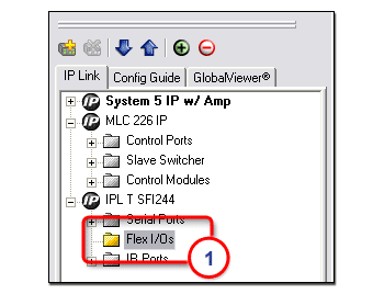
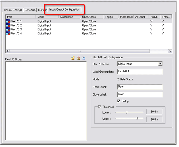
Flex I/O PortsFlex I/O ports are found on the following devices:
Flex I/O ports can be configured in three different ways:
Flex I/O ports allow IP Link devices to accept an input voltage and then send out a serial command to trigger another event. These ports can support TTL and analog signals from 0 to 24 volts, allowing a wide variety of devices to be controlled and monitored. Analog inputs to Flex I/O portsFlex I/O ports can be configured to receive analog voltages for use with photo sensors, level feedback, strain gauges, thermocouples, variable potentiometers and other devices. Incoming analog voltages from 0 to 24 volts are sampled with 12-bit precision. For example, a thermal sensor installed in an equipment rack can be connected to one of the Flex I/O inputs and the IP Link device can be configured to send an e-mail message, turn on auxiliary cooling fans, and turn off equipment if the rack temperature exceeds a specified temperature value. Digital inputs to Flex I/O portsConfigured as digital inputs, the Flex I/O ports can connect to switches, motion sensors, moisture sensors and tally feedback. This allows you to receive status from a variety of devices including projector lifts, motorized projection screens, room partition switches, and push buttons. Digital outputs from Flex I/O portsWhen configured as digital outputs, the Flex I/O ports can drive LEDs, 24 volt incandescent lamps, an additional external power supply, or other devices that accept a TTL input signal. For applications that require contact closure control, the Flex I/O ports can interface with an Extron IPA T RLY4 (an IP Link accessory featuring four isolated relays). |
![]()
|
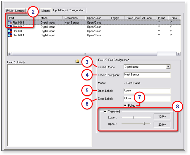
To configure a Flex I/O port:
|
|
|
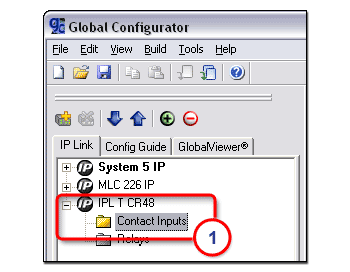
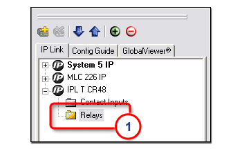
Contact Input Ports and Relay PortsThe IPL T CR48 has:
The Contact Input ports and Relay ports can be used to control screens, timers, lights, motion sensors, and more as shown below. |
|
|
![]()
Contact Input portsContact Input ports can receive 0 to 5 VDC TTL input signals from devices such as screens, timers, lights, and motion sensors in order to track the status of such devices. |
|
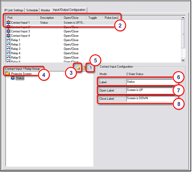
To configure a Contact Input port:
|
|
|
|
Note:
Before changes
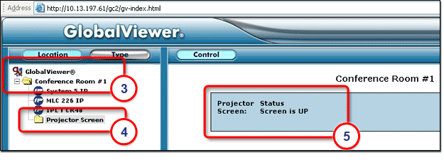
are viewable in GlobalViewer To view the Contact Input label in GlobalViewer:
The following information is displayed on the Control page (5):
Note: If the current status of the projector screen is down, the close label (such as Screen is DOWN) is displayed here.
|
|
Relay portsRelay ports provide the capability to control a wide range of AV devices such as screens, lights, and projector lifts. |
|
To configure a Relay port:
|
|
Note: See the Mode options subsection below, for a description of the different mode options.
|
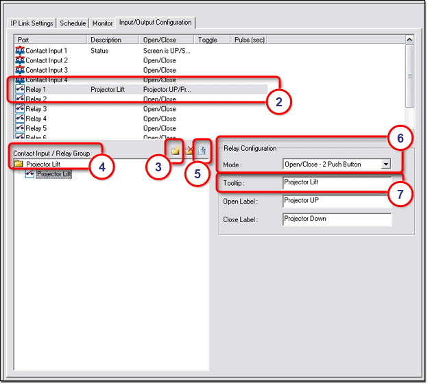
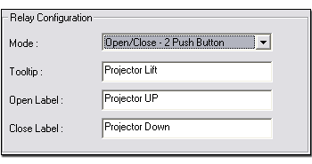
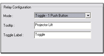
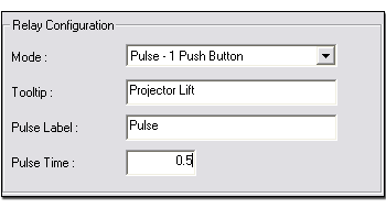
Mode optionsThe button labeling options in the Relay Configuration section differ depending on which mode was selected in step 6 above.
In the Open Label field, enter the desired Open label. In the Close Label field, enter the desired Close label. |
|
|
|
|
|
|
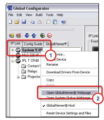
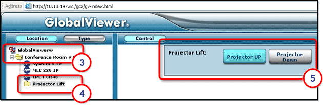
Note: Before changes are viewable in GlobalViewer, you must perform the build and upload process in Global Configurator. To view the Relay button captions in GlobalViewer:
The following information is displayed on the Control page (5):
|
|
![]()