MLS Port Tab

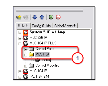
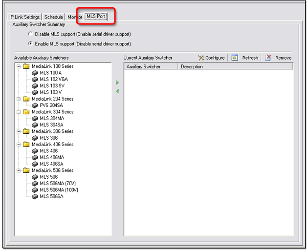
The MLS Port tab is used to add an AV switcher to your network configuration.  This switcher is used with a MediaLink Controller (MLC) to:

  • Increase the number of available input ports.

  • Enhance the audio controls.

  • Simplify the cabling installation.

The MLS Port tab is available with the following devices:

  • MLC 226 IP

  • MLC 104 IP Plus

  • MLC 104 IP

  • MLC 104 Plus

  • MLC 104

Note:  You can add and configure an AV switcher without a physical switcher connection.  However, the switcher must be physically connected for the GC build and upload process to be successful.
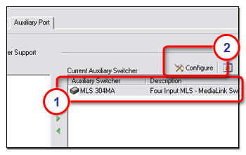
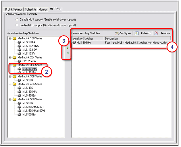
Adding an AV Switcher

To add an AV switcher to your network configuration:

  1. In the IP Link® Tree window, select the MLS port of an MLC device.  The MLS Port tab is displayed (see below).

  2. In the Available Auxiliary Switchers section, select an auxiliary switcher.

  3. Click the Right Arrow button.  The auxiliary switcher is now displayed in the Current Auxiliary Switcher (4) section and in the IP Link Tree window.

Configuring an AV Switcher

To configure an AV switcher:

  1. In the Current Auxiliary Switcher section, select an auxiliary switcher.

  2. Click the Configure button.  The Configure <switcher> dialog box opens (see below).

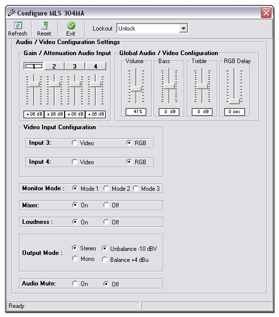
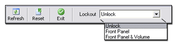
The toolbar options in the Configure <switcher> dialog box include:
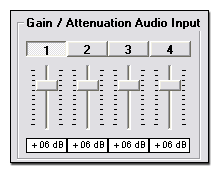
  • Refresh Connects to the attached AV switcher to send or receive current data

  • Reset Resets the AV switcher to its factory default state

  • Exit Saves the settings and closes the dialog box

  • Lockout

  • Unlock Allows input and volume changes via the front panel of the AV switcher

  • Front Panel Locks the front panel of the AV switcher so that no input changes can be made

  • Front Panel & Volume Locks the front panel and volume control of the AV switcher so that no changes can be made

Gain / Attenuation Audio Input

The controls in the Gain / Attenuation Audio Input section set the gain levels for the four audio inputs on the AV switcher.
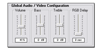
     

Global Audio / Video Configuration

The Global Audio / Video Configuration section provides Volume, Bass, and Treble controls that affect all of the audio channels on the AV switcher.

The controls also provide RGB Delay (Triple-Action Switching™).

Triple-Action Switching is when the RGB input signal is muted during switching until the projector has time to sync up to the new image.

This prevents viewers from seeing a scrambled image that may occur during switching.  Viewers will instead see a blank screen for the duration of the RGB Delay setting.  The RGB Delay options range from 0 to 5 seconds in 0.5-second increments.
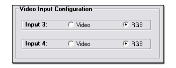
Video Input Configuration

Input ports 3 and 4 on the AV switcher are capable of accepting either RGB (3 or 5 wire) or composite video
(1 wire) inputs.

Adjust the settings in the Video Input Configuration section to identify which type of input is present on ports 3 and 4 of the AV switcher.  
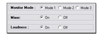
Monitor Mode

AV switchers have a local monitor output connector whose output is dependent on the currently selected input signal type and the Monitor Mode setting.

Options for the Monitor Mode setting include:

  • Mode 1 (RGB Follow Mode) If all configurable inputs are RGB and the selected input is 1, 2, or 3, the highest numbered RGB input signal is present on the Monitor Output connector.

  • Mode 2 (Distribution Amplifier Mode) If any configurable input is S-video or composite video, there is no monitor output.  If all configurable inputs are set for RGB, the highest numbered input signal is present on the Monitor Output connector.

  • Mode 3 (Standard Mode) If the selected input is S-video or composite video, there is no monitor output.  If the selected input is RGB, that RGB signal is routed to the monitor output.

The table below summarizes the Monitor Mode options.

IP Link Device

Monitor Mode

Selected Input

Input Condition

Monitor Output

MLS 304MA

MLS 304SA

1 / RGB Follow


1 or 2


3 and 4 = RGB

Input 4

3 or 4

3 and 4 = RGB

Selected Input

3 or 4

3 or 4 = Composite Video

None

2 / DA


Any


3 and 4 = RGB

Input 4

Any

3 or 4 = Composite Video

None

3 / Standard


Any Composite Video


N/A

None

Any RGB

N/A

Selected Input

MLS 406

MLS 406MA

MLS 406SA

1/ RGB Follow


1,2, or 3


4,5, and 6 = RGB

Input 6

4,5, or 6

4,5, and 6 = RGB

Selected Input

4,5, or 6

4,5, or 6 = S-video or Composite Video

None

2 / DA


Any


4, 5, and 6 = RGB

Input 6

Any

4, 5, or 6 = S-video or Composite Video

None

3 / Standard

Any S-video or Composite video

N/A

None

4, 5, or 6

4,5, or 6 = RGB

Selected Input


Mixer

AV switchers have an Aux/Mix input that accepts mono line level audio signals, which can be mixed with the current input.  Use the Mixer control to turn the mixed audio function on or off.  You can select one of the following radio buttons for the Mixer setting:

  • On

  • Off

Loudness

The Loudness control boosts low and high frequencies to compensate for the normal decreased hearing ability of the human ear at low volume levels.  Use this control to turn the Loudness function on or off.  You can select one of the following radio buttons for the Loudness setting:
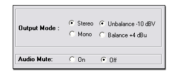
  • On

  • Off

Output Mode

You can select one of the following radio buttons for the Output Mode setting:

  • Stereo

  • Mono

  • Unbalance -10 dBV

  • Balance  +4 dBu

Audio Mute

You can select one of the following radio buttons for the Audio Mute setting:

  • On

  • Off