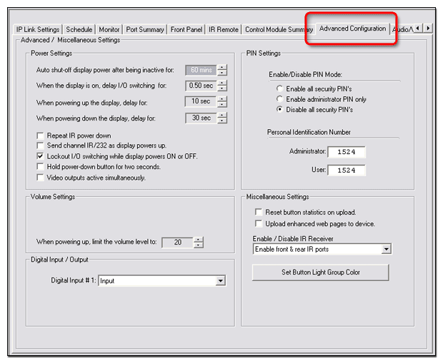
Advanced Configuration Tab

The Advanced Configuration tab is present if a System 5 IP or MediaLink® Controller (MLC) or one of their control ports is selected in the IP Link® Tree window.  The Advanced Configuration tab varies slightly depending on which product is selected and has the following functions:

Details for each function are provided below.  Differences between the System 5 IP and MLC screens are identified.

Power Settings

System 5 IP

MediaLink Controller (MLC)

The fields within the Power Settings section are typically populated by the selected device driver, but are user-selectable (adjustable) as described below.

  • Auto shut-off display power after being inactive for Powers off the display if there is no display activity for user-selectable inputs of 0 to 720 minutes in 30-minute increments.

  1. When display is on, delay I/O switching for After an input switch, this feature prevents the occurrence of a second input switch for the specified duration (0 to 5 seconds in 0.5-second increments).  This allows the projector to sync to the input signal before switching can occur again.

  2. When powering up, delay for Sets the time for which the display power-on indicator blinks during power-up before it lights solid, indicating the display is warmed up and ready for use.  
    User-selectable inputs are 0 to 300 seconds in 2-second increments.

  3. When powering down, delay for Sets the time for which the display power-off indicator blinks during power-down, before it lights solid, indicating the display has cooled down and the power-down sequence is complete.  

  4. Repeat IR Power down Many projectors require that a remote control power-off button be pressed twice before the projector powers down.  This check box sends a power-down command twice if the remote control power-down button is pressed, eliminating the need to physically press the button twice.

  5. Send Channel IR/232 as display powers up Sends the currently selected video input to the display when the display is powered on.  If this option is not selected, the display powers up displaying the input that was selected when the display was last powered  down.

  6. Lockout I/O switching while display powers ON or OFF This option prevents all input selection changes during the display power-up or power-down sequence.

  7. Hold power-down button for two seconds Requires the front panel display power-down button be held down for 2 seconds before the power-down sequence occurs.  This prevents accidental display shutdowns.

System 5 IP only

  1. Video outputs active simultaneously Some projectors require an active signal at each of their input ports in order to work properly.  The System 5 IP keeps the RGB output active at all times.  If you want to keep either the composite video or S-video output active, along with the RGB output, in order to support the requirement of the projector for all inputs active, select the Video outputs active simultaneously check box.

Volume Settings

System 5 IP

  • When power up, limit the volume level to This option sets the volume limit during power-up to a user-selectable level of 0 to 40 in single-digit increments.

MediaLink Controller (MLC)

There are two types of device driver options available for the volume adjustment on a MediaLink (MLC) device:

  • Up and Down buttons These buttons drive the volume up or down depending on which button is pressed.

  • Slider 0 (no volume) is on the left and a numerical value (high volume) is on the right.


If you configure the front panel Volume Up and Down buttons (1) in GC with the Volume Up and Down command (2), the volume control on the MLC front panel interfaces electronically with the device similar to Up and Down buttons.

If you configure the front panel Volume Up and Down buttons (1) with the Volume Range command (3) the volume control on the MLC front panel interfaces electronically with the device similar to a volume slider.

If you choose the Up and Down command in the Button Operations section of the Front Panel tab, you must also choose the Increment / Decrement option in the Volume Settings section of the Advanced Configuration tab (see below right).

If you choose the Range command in the Button Operations section of the Front Panel tab, you must also choose the Range option in the Volume Settings section of the Advanced Configuration tab (see below right).

When adjusting the volume, use  You can select Range or Increment/Decrement from the
drop-down list.  Volume control for a projector, display, or audio output device involves one of two methods:

  • Selecting a setting within a specific range of values

  • Sending a simple command to increment or decrement the volume by a fixed amount.

Select the appropriate method for the equipment you are using.  See the user guide for the display or audio device.


When you select the Range option, the Maximum volume steps for the projector field becomes active.

This field is initially populated by the device driver with the maximum number of volume steps available for the associated projector.

To limit the maximum volume level of the projector, adjust this number to the desired level.  You can only lower the maximum volume number.  You cannot raise this number above the initial setting provided by the associated device driver.

The volume control indicator lights on the MLC behave in the following manner, depending on the setting of the When adjusting the volume, use field.

  • Range As the knob is turned clockwise, increasing volume, five indicators come on, one at a time, from bottom to top and remain lit.  The top indicator flashes when the volume reaches its upper limit.  

    As the knob is turned counterclockwise, decreasing volume, five indicators turn off, one at a time, from top to bottom.  The bottom indicator flashes when the volume reaches its lower limit.

  1. Increment / Decrement As the knob is turned clockwise, increasing volume, indicators flash on in a bottom-to-top sequence, then quickly go out.

    As the knob is turned counterclockwise, decreasing volume, the indicators flash on in a top-to-bottom sequence, then quickly go out.

The other fields within the MLC Volume Settings section are:

  • When powering up, limit the volume level to This sets the volume limit during power-up within a range of 0 to 100 in single-digit increments.

  • Volume encoder scaling factor (0 - 255) This feature allows you to slow down the volume knob (the encoder) on the front panel of the MLC.  The value entered in the encoder scale area is the encoder speed scaling factor.  A value of 1 scales the speed down by a factor of 2 (the MLC issues commands at
    1/2 speed), a value of 2 scales by a factor of 3 (the MLC issues volume commands at 1/3 speed), and so forth.  A factor of zero sets the MLC for no scaling (the volume encoder works at full speed).


This feature addresses a problem that occurs with some projectors that use a range type volume control.  When the MLC encoder knob controls projector volume, sometimes the MLC sends the volume commands faster than the projector can detect and process them.  The projector does not detect some of the volume change commands, resulting in a choppy volume ramp.

Encoder scaling gives the programmer the ability to slow the knob down to a speed the projector can handle.  The drawback is that you must turn the knob more to change from minimum to maximum volume.  It is up to you to find a balance between smooth audio ramping and the number of knob turns needed to cover the volume range.  This requires trial and error for each projector exhibiting this problem.

Although this feature is mainly for range type volume control, it applies to any range type command programmed to be executed by the volume knob.

PIN Settings

System 5 IP

MediaLink Controller (MLC)

The PIN Settings section allows you to enable or disable the requirement to enter a PIN prior to accessing the device front panel buttons.  The options are:

  • Enable all security PINs Requires an administrator or user to input a PIN prior to accessing the front panel buttons

  • Enable administrator PIN only Requires an administrator to input a  PIN prior to accessing the front panel buttons.  This option locks the front panel buttons against all other attempts.

  • Disable all security PINs Allows all users to have access to the front panel buttons.

  • Administrator Displays the current Administrator PIN and allows the user to input a new PIN.

  • User Displays the current user PIN and allows the user to input a new PIN.

The factory default PINs are:

Device

Admin

User

System 5 IP

1524

1524

MLC 226

1346

1346

MLC 104 IP Plus

1423

1423

MLC 104 IP

1423

1423

MLC 104

1423

1423

Note:  See the respective user guide for instructions on how to enter a PIN on the device front panel.

Digital Input / Output

System 5 IP

The System 5 IP has one digital input port that can be configured as an input or power sensor.  

To configure the port:

From the Digital Input #1
drop-down list in the Digital Input / Output section, select one of the following:

  • Input - Select this option for any type of digital input status signal.

  • Power Sensor - Select this option if there is a power status output from a display device.

Note:  Use the Schedule and Monitor tabs to select conditions, actions, and e-mails in response to the input or power sensor signal.

MediaLink Controller (MLC)

The MLC has one Digital I/O port that can be configured as an input, output, input with pull-up, or output with pull-up.  The MLC also has one digital input port that can be configured as an input or power sensor.

To configure the ports:

  1. From the Digital I/O #1
    drop-down list in the
    Digital Input / Output section, select one of the following:

  2. Input Select for any type of digital input signal.

  3. Output Select for any type of digital output signal.

  4. Input With Pull-up Select for any type of digital input signal that requires a pull-up resistor.

  5. Output With Pull-up Select for any type of digital output signal that requires a pull-up resistor.

  1. From the Digital Input #2 drop-down list, select one of the following:

  2. Input Select for any type of digital input status signal.

  3. Power Sensor Select if there is a power status output from the display.

Notes:    Use the Schedule and Monitor tabs to select test conditions, actions, and e-mails in response to the input, input with pull-up, or power sensor signal.

Use the
Schedule and Monitor tabs to select the appropriate port and action or e-mail to be associated with the output or output with pull-up signal.

Miscellaneous Settings

System 5 IP

MediaLink Controller (MLC)

The settings in the Miscellaneous Settings section include:

  • Reset button statistics on upload The System 5 IP and MLC devices store front panel button statistics in non-volatile memory.  If you would like to reset these statistics each time you perform a build and upload cycle, select the Reset button statistic on upload check box.

  • Upload enhanced web pages to device The enhanced web pages include an improved graphical representation of the device front panel that is displayed in the System Status web page.  

To view the enhanced web pages:

  1. In the Miscellaneous Settings section, select the Upload enhanced web pages to device check box.

  2. Perform a build and upload cycle.

  3. In the IP Link Tree window, right-click on the device.

  4. Select Open System Status Page from the drop-down list.  The System Status page is displayed.

  5. Click the Control tab.  This launches the enhanced web page.

  1. Enable / Disable IR Receiver The System 5 IP and MLC devices have two Infrared (IR) receiver ports by which the device can be remotely controlled.  Enable or disable these IR receivers by selecting one of the following options from the Enable / Disable IR Receiver drop-down list:

  2. Enable front & rear IR ports

  3. Disable front & enable rear IR ports

  4. Enable front & disable rear IR ports

  5. Disable front & rear IR ports

Set Button Light Group Color

If you have assigned button groups on the Front Panel tab, you can assign different colors for the buttons in each grouping.

The color options for the buttons, themselves, are:

  • Amber (default)

  • Green

  • Red

To assign a color to a specified button group:

  1. In the Miscellaneous Settings section, click Set Button Light Group Color.

  2. Identify the desired group.

  3. Select the desired color from the associated drop-down list.

  4. Click OK.

When you assign multiple buttons to a grouping, only one of the buttons can be activated at a time.  

When you assign a color to a button group, the activated button illuminates with the assigned color on the physical front panel of the device and in the representation of the front panel in the GlobalViewer® interface.

Note:  On a System 5 IP device, only the front panel Room buttons can be configured in groups.